
Written by Alexander Christian Greco
With the Help of ChatGPT
A Functional View of Computer Engineering

1. Signal Systems: The Physical Language of Computation
At the lowest level, computers operate not on numbers or symbols, but on electrical signals. A signal system defines how physical phenomena—typically voltage or current—are used to represent information reliably inside electronic hardware.
1.1 Analog vs. Digital Signals
- Analog signals vary continuously over time and amplitude.
- Digital signals use discrete levels—most commonly two—to represent information.
Modern computers are digitally logical but physically analog. Every digital signal is implemented using real electrical properties governed by physics and electrical engineering.

In standard CMOS logic:
- Logic 0 ≈ 0 V
- Logic 1 ≈ a fixed supply voltage (e.g., 1.2 V, 3.3 V)
Crucially, these are ranges, not exact values. This tolerance enables robustness against noise.
1.2 Noise, Thresholds, and Signal Integrity
Signal systems must handle:
- Thermal noise
- Electromagnetic interference
- Voltage drops and crosstalk
- Timing skew and jitter
To manage this, engineers define:
- Noise margins – safe voltage ranges for 0 and 1
- Threshold voltages – decision boundaries in logic gates
- Rise/fall times – how fast signals transition
- Propagation delay – how long signals take to travel
These parameters directly constrain clock speed, power consumption, and chip size.

1.3 Clocking and Synchronization
Most CPUs are synchronous systems, coordinated by a global clock signal.
The clock:
- Defines when signals are sampled
- Divides computation into discrete steps
- Sets the maximum operating frequency
Clock design is one of the hardest problems in modern processors, requiring:
- Low skew across billions of transistors
- Careful power distribution
- Precise timing closure
Without a stable signal system, higher-level computation collapses.
2. Digital Logic: Computation as Boolean Structure

If signal systems define how information exists physically, digital logic defines how information is transformed.
2.1 Boolean Logic Foundations
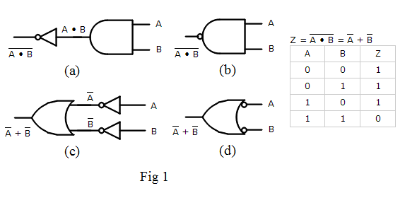
Digital logic is built on Boolean algebra, where variables take values {0,1} and are combined using operators:
- AND
- OR
- NOT
- XOR
- NAND / NOR (functionally complete)
Each operation is implemented as a logic gate, constructed from transistors acting as controlled switches.
2.2 Combinational Logic
Combinational circuits compute outputs purely from current inputs.
Examples:
- Adders and subtractors
- Multiplexers
- Comparators
- Arithmetic Logic Units (ALUs)
Properties:
- No memory
- Deterministic output
- Defined by truth tables or Boolean expressions
Combinational logic forms the computational core of arithmetic and decision-making.

2.3 Sequential Logic and State
To build systems, computers require memory.
Sequential logic introduces:
- State
- Feedback
- Time dependence
Key components:
- Latches
- Flip-flops
- Registers
- Counters
State is updated on clock edges, enabling:
- Instruction sequencing
- Data storage
- Pipeline stages
- Control flow
This is where digital logic becomes architectural.
2.4 Finite State Machines (FSMs)
Control units inside CPUs are often modeled as finite state machines, which:
- Encode control behavior
- Orchestrate instruction execution
- Manage pipelines, branches, and hazards
FSMs bridge raw logic and processor-level behavior.
3. The CPU: Organized Computation at Scale
The Central Processing Unit (CPU) is where signal systems and digital logic converge into a programmable machine.
3.1 Core CPU Components
A modern CPU consists of tightly integrated subsystems:
- Control Unit – directs operation sequencing
- ALU / Execution Units – perform arithmetic and logic
- Registers – fast, local storage
- Instruction Decoder – interprets machine instructions
- Caches – mitigate memory latency
- Clock and timing circuitry
All of these are built from logic gates, which are built from transistors, which are driven by electrical signals.
3.2 Instruction Execution Cycle
At a high level, CPUs follow a fetch–decode–execute loop:

- Fetch instruction from memory
- Decode opcode and operands
- Execute computation or control action
- Write back results
Each stage corresponds to specific logic blocks and clocked state transitions.
3.3 Pipelining and Parallelism
To improve performance, CPUs overlap instruction stages using pipelines.
Challenges include:
- Data hazards
- Control hazards (branches)
- Structural hazards
Solutions rely on:
- Forwarding logic
- Speculative execution
- Branch prediction
- Out-of-order execution
These mechanisms dramatically increase throughput but greatly increase design complexity.
3.4 Microarchitecture vs. Architecture
- Instruction Set Architecture (ISA) defines what the CPU does
- Microarchitecture defines how it is implemented
Multiple CPUs can share an ISA while using radically different logic designs, pipelines, and signal strategies.

4. How the Layers Interlock
Computer engineering is fundamentally hierarchical:
| Layer | Role |
|---|---|
| Signal Systems | Reliable physical representation |
| Digital Logic | Deterministic transformation |
| CPU Architecture | Programmable execution |
Design decisions propagate upward and downward:
- Signal noise limits clock speed
- Clock speed limits pipeline depth
- Pipeline depth shapes instruction scheduling
- Scheduling affects compiler and software design
This interdependence is why computer engineering spans electrical engineering, logic design, and computer architecture.
5. Why This Matters for Engineers
Understanding these layers enables engineers to:
- Optimize performance and power
- Debug timing and logic failures
- Design custom processors and accelerators
- Reason about hardware–software interaction
- Build reliable systems at scale
Whether designing embedded controllers, CPUs, GPUs, or AI accelerators, the same principles apply.
Conclusion
Signal systems give computers a physical voice, digital logic gives them reason, and the CPU gives them agency. Computer engineering is the discipline that binds these together into machines capable of executing abstract algorithms through concrete physical processes.
At its core, every computation is a carefully timed dance of electrons—guided by logic, constrained by physics, and orchestrated by architecture.
Leave a Reply